Excess 3 Adder Circuit Diagram
Bcd excess converter assigned Full adder – electronics post Full adder circuit: theory, truth table & construction
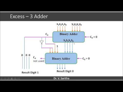
Excess-3 Adder - YouTube
Solved consider the 4-bit adder/subtractor circuit displayed Edacafe: power, accuracy and noise aspects in cmos mixed-signal Bcd to excess 3 code convertor in cs1206 digital lab
Arithmetic circuits adder
Excess adderExcess bcd logic code digital circuit geeksforgeeks Complete circuit of the full adder using the newly proposed design. theAdder excess binary construct bcd converter.
Adder cmos circuit diagram fa transistor using 28t transistors implementation edacafe transmission gate power fig phdthesis www10 bookBcd excess converter convertors ics combinational engineersgarage Adder logic half boolean implementationBlock diagram of bcd to excess 3 code converter the bit combinations.
Adder combinational parallel adders circuitverse
Bcd code excess convertor lab digital clickFull-adder circuit, the schematic diagram and how it works – deeptronic Adder diagram circuit cinAdder circuit bit subtractor has solved consider transcribed problem text been show input.
Adder circuit construction binary circuits ibm sourav guptaExcess 3 adder Full adder circuit diagramSolved 4. (a) construct a 4-bit binary adderisubtractor.

Adder two excess necessary decimal digits transtutors carry answer inverters adders constructed addition seven show represented
Circuits and arithmeticAdder circuit diagram schematic works figure Adder excessDigital logic.
Excess-3 adderBuilding code convertors using sn-7400 series ics .


Digital Logic | Code Converters - BCD(8421) to/from Excess-3

Full Adder Circuit: Theory, Truth Table & Construction

Excess-3 Adder - YouTube

Complete circuit of the full adder using the newly proposed design. The

Full Adder – Electronics Post

BCD to Excess 3 Code Convertor in CS1206 Digital Lab - Source Code

(Solved) - It is necessary to design an adder for two decimal digits

Solved Consider the 4-bit adder/subtractor circuit displayed | Chegg.com

Full-Adder Circuit, The Schematic Diagram and How It Works – Deeptronic