Design Full Adder Using 4*1 Mux
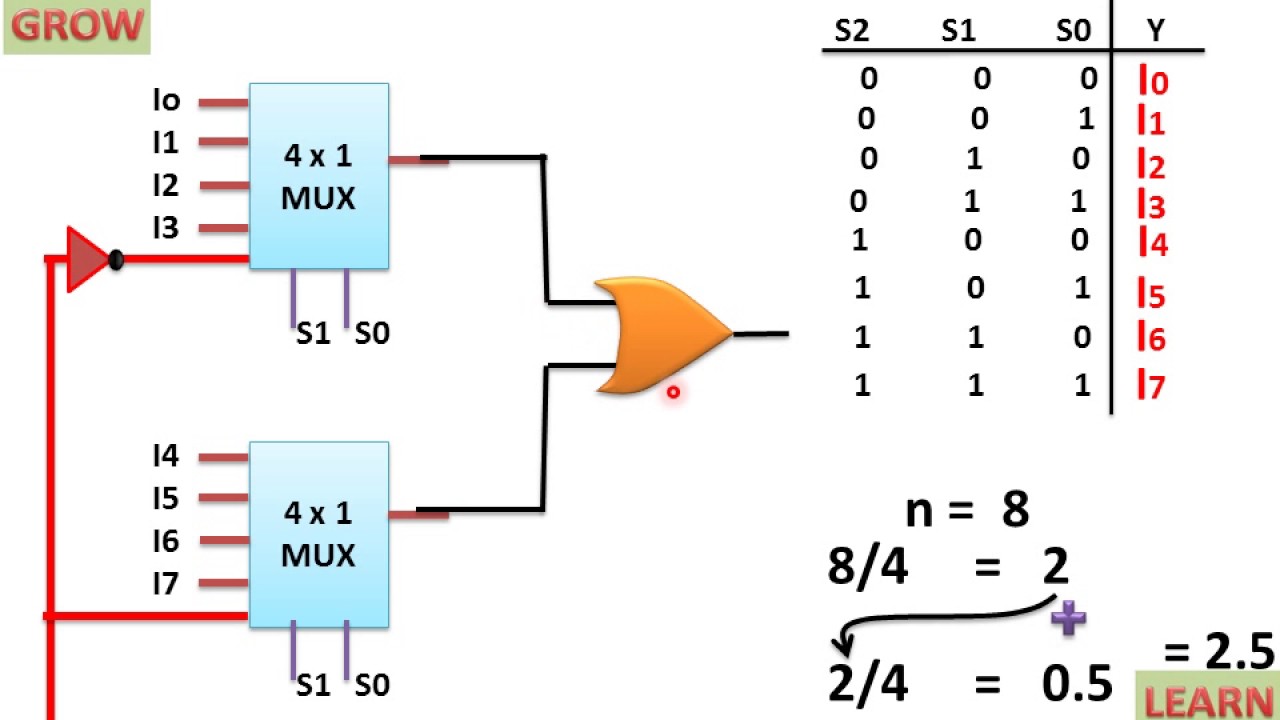
8x1 mux logic diagram : using 8 1 multiplexers to implement logical 8x1 mux multiplexer 4x1 logic implementation implement multiplexers logical 2x1 hardware Adder multiplexer
Full Adder | SlayStudy
Adder cmos vlsi Adder mux Full adder using 4:1 mux
Cs150 spring 1997 quiz 2 solutions
Adder multiplexer(pdf) vlsi design of power efficient 4-bit signed adder for arithmetic Adder cmos arithmetic vlsi efficientAdder mux cs150 quiz 1997 solutions spring characteristics describe counter function.
Full adderAdder logic diagram hackaday expression calculations obviously both final use now circuit Multiplexer circuit logic gate mux using subtractor implementation digital inverter symbol bit line multiplexers selector surrey ac electronics above source(pdf) vlsi design of power efficient 4-bit signed adder for arithmetic.
Designing circuits with switching algebra
Full adder .
.


(PDF) VLSI DESIGN OF POWER EFFICIENT 4-BIT SIGNED ADDER FOR ARITHMETIC

(PDF) VLSI DESIGN OF POWER EFFICIENT 4-BIT SIGNED ADDER FOR ARITHMETIC

multiplexer - Design a full subtractor using 4 to 1 MUX and an inverter

Full Adder using 4:1 MUX | Download Scientific Diagram

CS150 Spring 1997 Quiz 2 Solutions

Full Adder | SlayStudy

Full Adder | SlayStudy